Typical X-ray diffraction experiments provide the structure factor moduli, while the relative phases are lost. Recovery of the phase information is crucial for the ab-initio crystal structure solution and is referred in Crystallography as the phase problem. In EXPO2014, the default strategy used to solve this problem is based on the application of the Direct Methods (DM) theory (Giacovazzo, 2013). DM are able to estimate phases directly from the structure factor amplitudes. The application of DM to powder data requires the previous decomposition of the full experimental powder pattern to extract single diffraction intensities for each reflection in the measured 2theta range. Owing to the peak overlap the estimates of the diffraction moduli are affected by unavoidable errors: this weakens the efficiency of DM (naively, wrong moduli will produce wrong phases), and still today makes crystal structure solution from powder data a challenge.
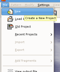
To run EXPO2014 for structure solution you need to create an input file (*.exp). You can create an input file accessing by graphic interface by the menu File > New.
You must specify the structure name, the profile count filename and its format, the type of radiation source. It is supposed that the cell parameters and the space group have been determined before, so fill the frame ‘Cell Parameters’ and ‘Space Group’. Activate the Structure Solution check button if you intend to perform the crystal structure solution process by Direct Methods. Otherwise, use the button Open to import an existing input file .exp; for example you could load the file cime.exp already existing in the directory ‘examples’. The following picture is an example of the input file for crystal structure determination of the cimetidine compound.
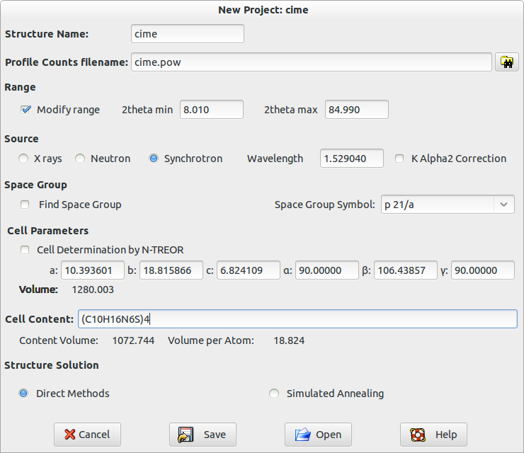
When you press the button Save, an input file cime.exp is created and automatically loaded by the program for the structure solution process by DM.
%structure cime
%job structure cime
%data
pattern cime.pow
content (C10H16N6S)4
wavelength 1.52904
cell 10.6986  18.8181  6.8246  90.000  111.284  90.000
spacegroup p 21/n
synchrotron
%continue
The meaning of lines in the input file is contained in the chapter Commands of Expo2014 of this manual.
Alternatively to the creation of the input file by graphic interface, you can edit a new input file or modify an exiting one with a text editor and save it with extension .exp. Once a time the input file has been created, load the .exp input file from menu File > Load & Go.

Press the button ![]() in the toolbar and the following steps of the structure solution process will be automatically performed:
in the toolbar and the following steps of the structure solution process will be automatically performed:
1) Extraction of the integrated intensities from the powder diffraction pattern;
2) Normalization of the integrated intensities via Wilson method (Wilson, 1942);
3) Triplet invariants calculation and estimate of their phases via P10 formula (Cascarano et al., 1984);
4) Phasing of structure factors by using the tangent formula: more plausible sets of phases are generated, whose reliability is assessed via the CFOM figure of merit (Cascarano et al., 1992). In a default run, not more than twenty sets of phases with the largest CFOM values are stored and ranked in decreasing CFOM order.
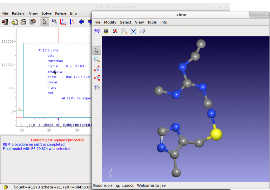
5) Fourier map (E-map) calculation and crystal structure optimization by using the normalized structure factor moduli and the set of phases corresponding to the largest CFOM value. The most intense peaks in the E-map are located and chemically interpreted. The obtained structure model is optimized and completed via automatic structure model optimization strategies.
More information about the structure solution process by Direct Methods are given in the chapter The steps of structure solution by DM.
Each step of the solution process by DM corresponds to a specific command in the input file for EXPO2014.
A lot of crystal structures are solved by EXPO2014 by default settings in few minutes and in completely automatic way.
Unfortunately you can’t always obtain the correct structure solution in default. In this situation two different strategies are suggested and can be applied at the end of the default run.
The ALLTRIALS procedure (Altomare at al., 2013)
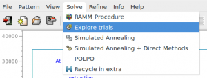
In a typical Direct Methods procedure more sets of phases (trials) are generated and no more than 20 of them are saved and ranked according to the combined CFOM figure of merit (estimating the quality of the trial) and only the best trial corresponding to the largest CFOM value is used to calculate a Fourier map. Because of unavoidable errors in the phases, the figure of merit can fail to evaluate the best trial, so it is strictly suggested to process the other trials by menu Solve > Explore Trials.
The following window is opened (the procedure has been applied to 2-Mercaptobenzoic acid compound, whose input file, merca.exp, is in the directory ‘examples’)
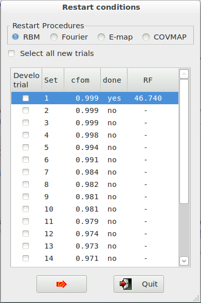 and the CFOM values, for each saved trial, can be read. The highest CFOM value could not correspond to the correct solution while subsequent different trials may be successful. This is particularly true when several nearly equivalent CFOM’s are available for different trials as in the picture. If the trial has been already developed (done=’yes’), you can read the RF figure of merit value that quantifies the agreement between the structure factors extracted from the experimental pattern and calculated by the model corresponding to the current trial.
Check the button in the first column to decide which trial will be developed and press the button ![]() . If you check the button Explore trials not processed yet, all the trials not already explored will be automatically selected and developed.
. If you check the button Explore trials not processed yet, all the trials not already explored will be automatically selected and developed.
You can choose three different actions for the structure model optimization (see later):
- RBM: Resolution Bias Modification is the default action for organic and metal organic compounds (Altomare et al., 2008a, 2008b; 2009, 2010a, 2010b).
- Fourier recycling: classical Fourier refinement, default choice for inorganic compounds (Altomare et al., 2006).
- E-map: the first electron density map calculated directly after the phasing process by Direct Methods.
- COVMAP: the covariance principle based completion (Altomare et al., 2012).
- Shift_and_Fix: the method based on random shift of part of the model for improving the solutions (Altomare et al., 2017).
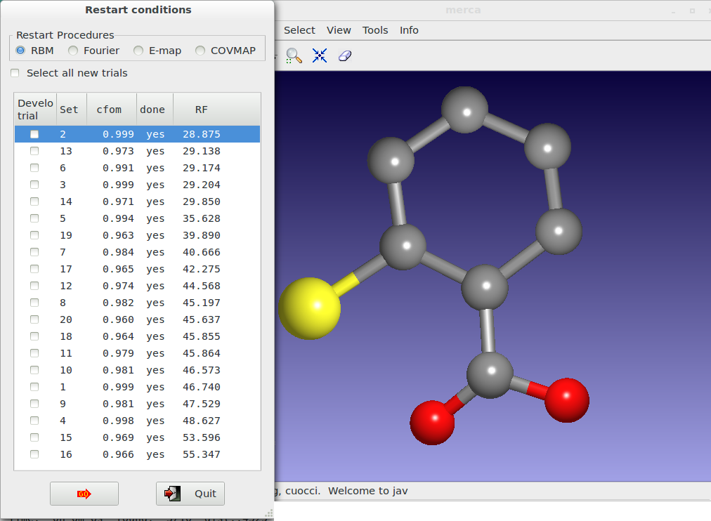
At the end of the procedure, all the trials appear ordered according to the RF value and the user can also view the model corresponding to each trial by mouse selection.
Alternatively to the graphical option, the use of the command %alltrials in the input file automatically activate the ‘Explore trials’ approach. An example of input file is here reported:
%structure merca
%job merca
%data
cell       7.885  5.976   14.949  90.0  100.48  90
space p 21/c
content    c 28 O 8 S 4 h 24
pattern    pd_0002.xy
wavelength 1.54056
%alltrials
The structure model obtained at the end of the default strategy, generally is a partially correct representation of the true model: some atoms are in correct positions but other ones are moved with respect to the correct positions or completely false. In this situation the user can try to improve the quality of the Fourier map obtained at the end of Direct Methods, by using different optimization strategies implemented in the EXPO2014 program:
- suitably weighted least squares (wLSQ) (Altomare et al., 2006), able to compensate the low accuracy of the intensities of strongly overlapped reflections. The procedure is automatically applied in case of inorganic compounds.
- the resolution bias correction algorithm (RBM) (Altomare et al., 2008a, 2008b; 2009, 2010a, 2010b) for reducing, in the electron density map, the errors caused by the limited experimental resolution: peak broadening, peak shift, intensity distortion. The correction has been developed in direct space (it represents the default choice in case of organic and metal organic compounds), in reciprocal space and in both direct and reciprocal space;
- the procedure of electron density modification based on the concept of covariance between points of the map (COVMAP) (Altomare et al., 2012). The procedure executes the following strategy: the structural model provided by the RBM procedure is submitted to COVMAP approach which suitably modifies the electron density map and successively submits the improved model to wLSQ analysis. The resulting new model is again modified by COVMAP and cyclically processed in the other two steps. The number of cycles depends on the structure complexity.
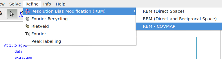
It is possible to graphically choose different RBM procedures for model optimization by Refine > Resolution Bias Modification (RBM) from the upper EXPO2014 menu.
Apply the RAMM (RAndom Model based Method) procedure
The new method RAMM (Altomare et al., 2013) has been developed and implemented in the EXPO2014 program for improving the ab-initio crystal structure solution process. When the available information consists of only the experimental powder diffraction pattern and the chemical formula of the compound under study, the structure solution classical approach follows two main steps: 1) phasing by Direct Methods and obtaining a structure model (this last is usually uncompleted and/or approximate); 2) improving the model by structure optimization techniques. The alternative RAMM approach skips step 1) and supplies a fully random model to step 2). Such model is then submitted to important structure optimization tools present in EXPO2014: wLSQ , RBM and COVMAP which are able to lead to the correct structure. RAMM is based on a cyclic process generating several random models which are then optimized. The process stops automatically when recognizes the correct structure.
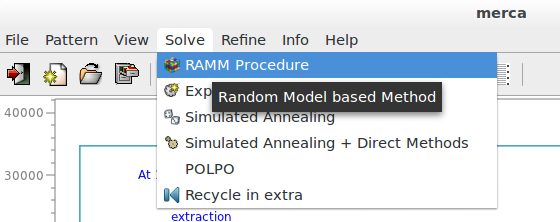
Click ‘RAMM’ on the menu ‘Solve’ to activate this alternative strategy for structure solution at the end of the default run of EXPO2014. The following pictures are related to 2-Mercaptobenzoic acid, whose input file is in the directory examples.
The procedure can take from some minutes to several hours depending on the complexity of problem (number of atoms, quality of data, data resolution). If more than one plausible solution is found they are ordered according to the RF value in an interactive list.
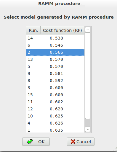
The selected model is visualized on the molecular viewer. Press ‘OK’ to accept the selected model.
When Direct Methods procedure fails, the RAMM approach can be a very useful tool to find the correct solution.
The use of the command %randomsolve in the input file automatically activate the RAMM approach. An example of input file is here reported:
%structure merca
%job merca
%data
cell       7.885  5.976   14.949  90.0  100.48  90
spacegroup p 21/c
content    c 28 O 8 S 4 h 24
pattern    pd_0002.xy
wavelength 1.54056
%randomsolve
The Shift_and_Fix method (Altomare et al. 2017) has been implemented in EXPO2014 with the aim of obtaining a complete and correct solution starting from an approximate, sometimes very rough, structure model. It can be activated by menu Solve>Explore Trials by selecting the corresponding button in combination with RBM (for organic/metal-organic structure) or Fourier recycling (for inorganic structures) selection. It can be applied to all the Direct Methods trial (suggested) or to preferred trial(s).
For the current trial, it starts from the model generated by Direct Methods and by cycling actions: shifts partly and randomly the model (possibly the most unreliable part of the model); combines Fourier map calculation and least‐squares cycles for relocating the shifted atoms onto positions which can finally be moved onto the true ones by the standard model optimization approaches; calculates the Fourier map by using coefficients which depend on the chemical content of the compound under study.
Click on ‘Explore Trials’ on the menu ‘Solve’ and select ‘Shift_and_Fix’ at the end of the default run of EXPO2014.
The number of options in the program is quite large. The optional strategies regard the improvement of both the decomposition process for carrying out more reliable reflection intensities and the Direct Methods performances. We give information about some other secondary strategies.
The improvement of the decomposition process
- It is important to provide good quality diffraction pattern. For example, it is recommended to reduce the pattern range in case of high noise signal at large 2theta values. In the input file for Expo2014, use the directive range in the command %data to select a portion of pattern or select Pattern > Range by the graphical interface.
- If a partial structure fragment has been located by the default run, it may be recycled in the extraction process to improve the extraction of the experimental integrated intensities (a graphic option must be selected). Click on Solve > Recycle in extra.
- The use of the random directive in the command %extraction, in the input file for Expo2014, activates the procedure for overcoming the Le Bail method tendency to equipartition the intensity of a group of strongly overlapped reflections. Based on a Monte Carlo approach, it may provide a set of more statistically meaningful extracted intensities.
- If the default run has revealed pseudo symmetry effects and, in particular, if the percentage of electron density affected by pseudo is large, it may be very useful to exploit that information in the extraction process: a graphic option is made available for activating the procedure.
The optimization of the Direct Methods procedure
- Magic integers procedure is an effective and simple way for starting a multi-solution process.
A random approach may be alternatively chosen in the phasing process by using the directive random in the command %phase (in the input file for Expo2014). - Second representation formula for triplet invariants proved much more powerful than first representation formula therefore it is used as a default for estimating triplet invariants. In case of failure, the user can choose P3 formula (directive cochran in the command %invariant in the input file for Expo2014) and/or conveniently increase the number of symbols in the phasing step (directive symbols followed by the number of symbols to be used in the command %phase).
- A check for possible pseudotranslational symmetry is always made by EXPO2014: if PSEUDO keyword is not activated the information is given but not used in the normalization routine and in the phasing process. The user can decide to use it by the directive pseudo in the command %normal in the input file for Expo2014.
- The value of the number of reflections actively used in the phasing process is fixed by EXPO2014 (nref). For some special structures the ratio “number of active triplets/nref” is too small (less than 10). Larger values of nref may improve the phasing procedure (directive nreflections followed by the number of reflections in the command %normal).
- High (or low) resolution reflections may occasionally play an important role in the phasing process by Direct Methods. Fixing an isotropical thermal factor lower (or larger) than that automatically provided by the Wilson plot in the normalization process by Direct Methods may be successful (directive bfactor followed by the isotropic thermal factor in the command %normal).
- An alternative space group should be carefully considered (directive spacegroup in the command %data).
- When the complete and correct solution is not attained, successive combined Fourier map calculations (Fo-Fc, 2Fo-Fc or Fo) and/or Rietveld refinement may be conveniently selected by graphical options. Click on Refine > Fourier and select the action.
For suggestions and bugs contact:
angela.altomare@ic.cnr.it
annagrazia.moliterni@ic.cnr.it
rosanna.rizzi@ic.cnr.it
corrado.cuocci@ic.cnr.it
Altomare, A., Cuocci, C., Moliterni, A., Rizzi, R., Corriero, N., Falcicchio, A. (2017). J. Appl. Cryst. 50 1812-1820.
Altomare, A., Cuocci, C., Giacovazzo, C., Moliterni, A.G.G., Rizzi, R. (2006). J. Appl. Cryst. 39 558-562.
Altomare, A., Cuocci, C., Giacovazzo, C., Kamel, G. S., Moliterni, A. & Rizzi, R. (2008a). Acta Cryst. A64, 326-336.
Altomare, A., Cuocci, C., Giacovazzo, C., Moliterni, A. & Rizzi, R. (2008b). J. Appl. Cryst. 41, 592-599.
Altomare, A., Cuocci, C., Giacovazzo, C., Moliterni, A., Rizzi, R. (2009). Acta Cryst. A65, 183-189.
Altomare, A., Cuocci, C., Giacovazzo, C., Moliterni, A., Rizzi, R. (2010a). J. Appl. Cryst. 43, 798-804.
Altomare, A., Cuocci, C., Giacovazzo, C., Moliterni, A., Rizzi, R. (2010). Z. Kristallogr. 225, 548-551.
A. Altomare, C. Cuocci, C. Giacovazzo, A. Moliterni and R. Rizzi (2012). Acta Cryst. A68, 244-255.
A. Altomare, C. Cuocci, C. Giacovazzo, A. Moliterni, R. Rizzi, N. Corriero and A. Falcicchio (2013). J. Appl. Cryst. 46, 1231-1235.
A. Altomare, C. Cuocci, C. Giacovazzo, A. Moliterni and R. Rizzi (2013). J. Appl. Cryst. 46, 476-482.
Cascarano, G., Giacovazzo, Camalli, M., Spagna, R., Burla, M. C, Nunzi, A. & Polidori, G. (1984). Acta Cryst. A40, 278-283.
Cascarano G., Giacovazzo C. & Guagliardi A. (1992). Acta Cryst. A48, 859-865.
Giacovazzo, C. (2013). Oxford: IUCr/Oxford University Press.
Wilson, A. J. C. (1942). Nature, Load 150, 152.